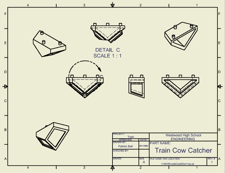
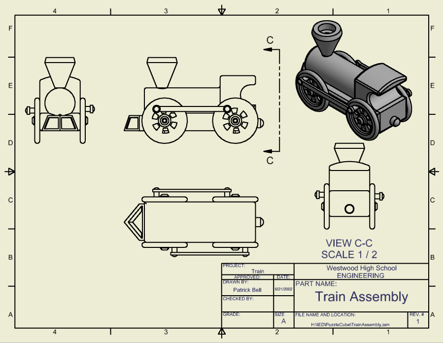
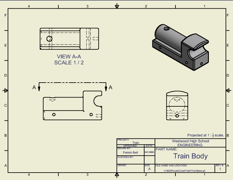
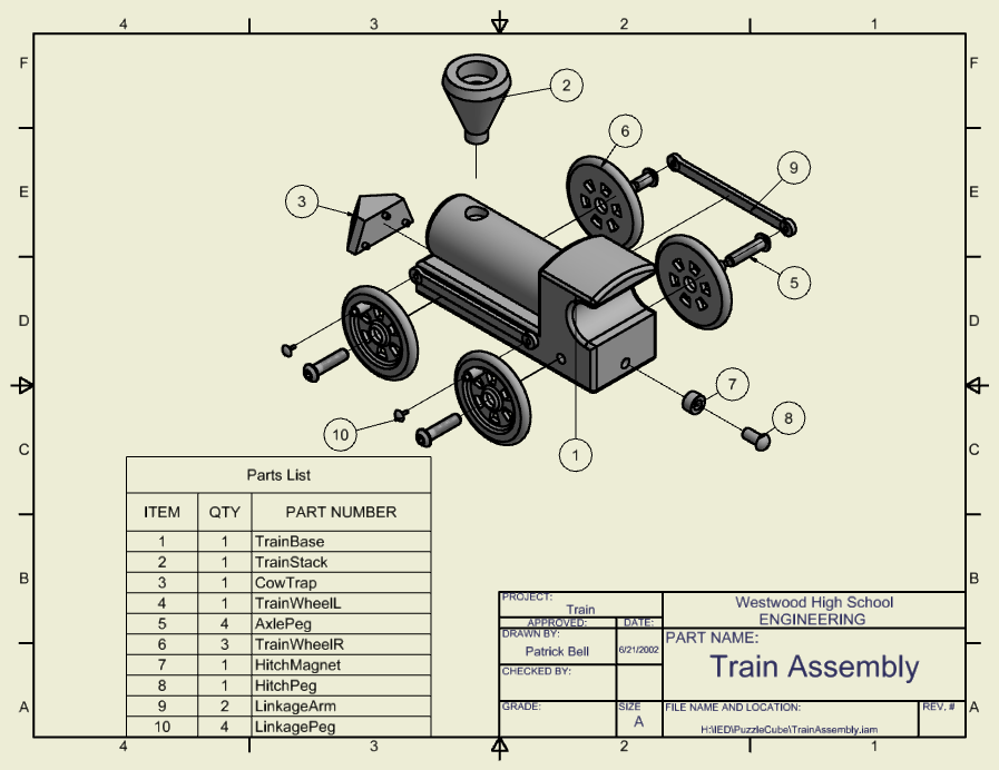
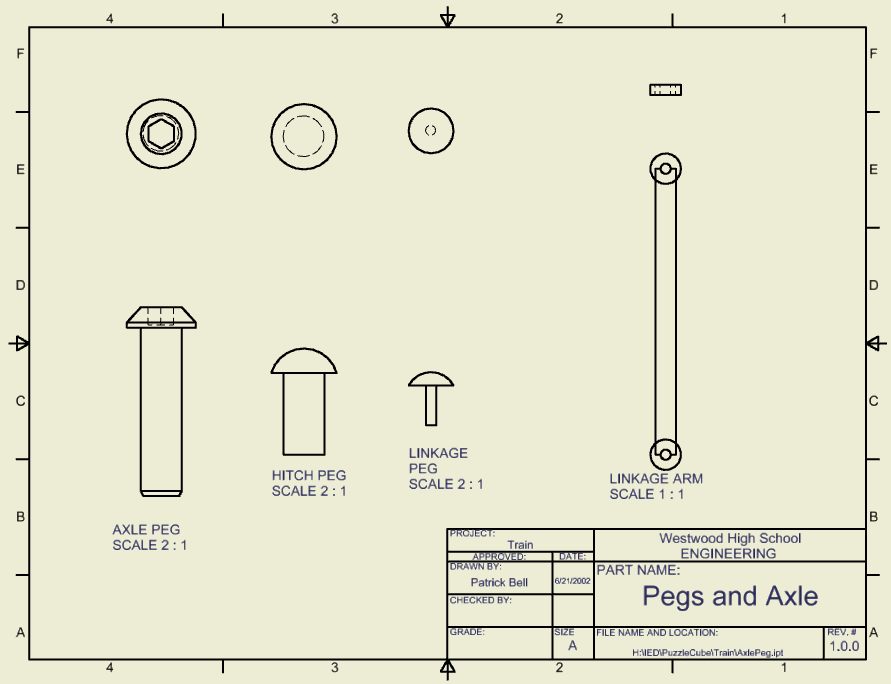
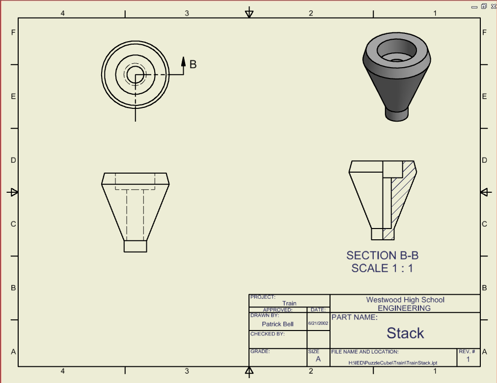
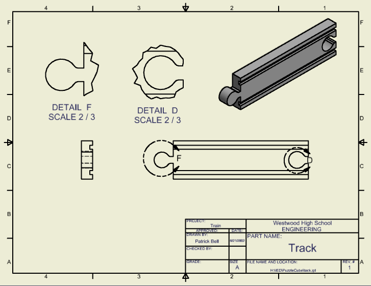
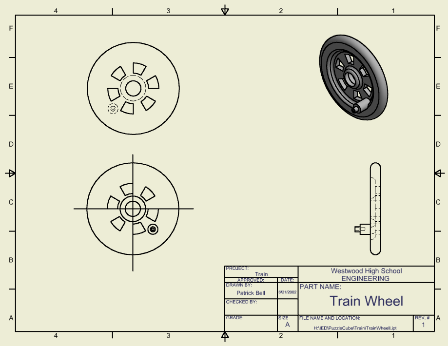
For this assignment, we created a model train following certain engineering sheets with proportions and general shapes. We replicated these in CAD software.
Conclusions
1.) Different line conventions are used to properly display different elements of the final 3D figure.
2.) Section views are used to get an interior view of the model at hand.
3.) Auxiliary views are used to get a greater sense of detail of interior and hidden features of models.
4.) The symbols can be used to visually represent what kind of measurement is being used.
5.) It allows for scaling the train properly, and prevents forcing a fixed overall size.
6.) Flush, mate, insert are the three constraints available in this CAD program.
7.) They allow for precise measurements, properly computer generated shading, and overall a faster process for the amount of precision that it provides.
